Go Wireless! Step 1: Footswitch
The Concept:
Build a completely wireless laser harp generator controller using cheap marketplace modules
The system:
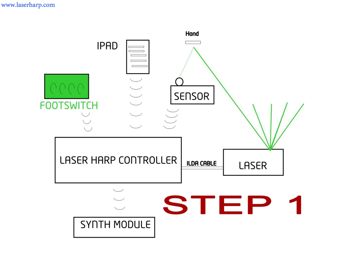
A standard laser harp system contains:
a laser harp generator connected to a projector with ilda connection, a wired footswitch for basic operations, a wired sensor to detect hands on beams, a wired connection with a keyboard or synth module or PC ( called MIDI or MIDI-USB).
The goal is to get rid of wires when possible: we start from the Footswitch. Let's cut the wire!
You need:
1 Kromalaser KL 3d-EVO board + Laser sensor module ( buy from www.kromalaser.com price for students: Euro 150 )
1 footswitch with 4 pushbuttons normally open type ( buy from Thomann: Eurolite LED KLS RGB Footswitch: Euro 40)
1 remote control 4ch based on PT2262 (buy on the bay, search "2262/2272 4CH Key 315MHZ Wireless Remote", Euro 5 both)
1 4 ch receiver based on PT2272 (as above)
Some wires and soldering iron
soldering skill :)

The Eurolite Footswitch:
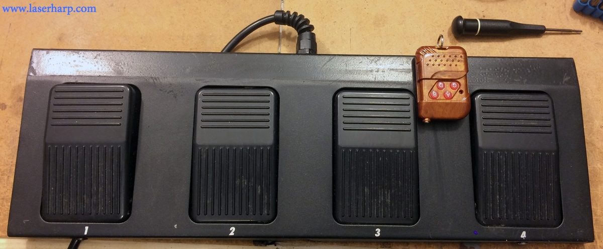
We start dismounting the footswitch and the remote controller. Just unscrew the covers on both of them.
We find 4 pairs of wires in the footswitch and 4 switches on the remote. they must be connected with 4 pair of wires.
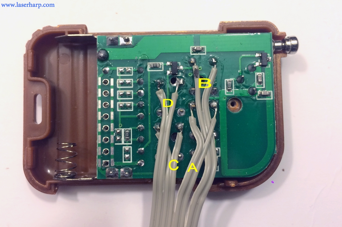
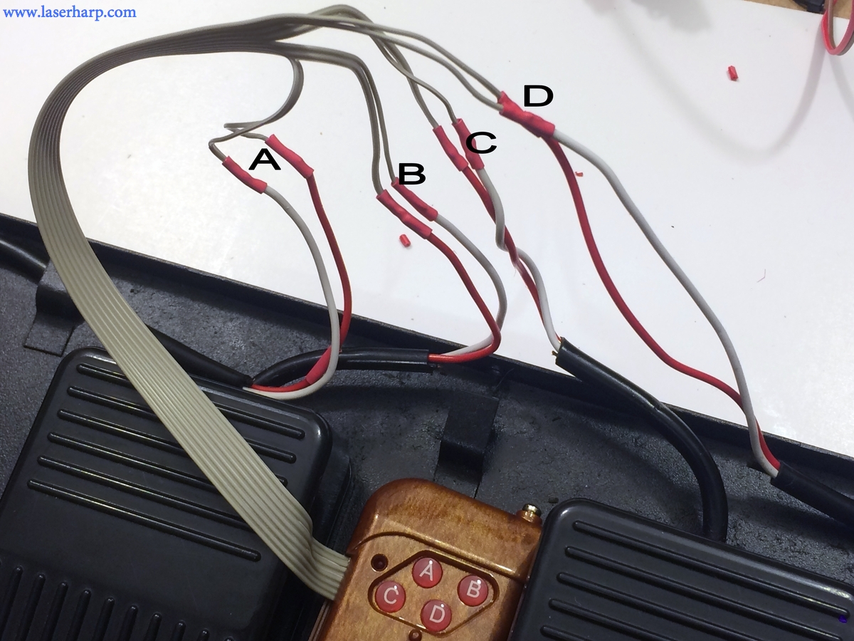
Take away the battery from the remote and solder 4 pairs of wires as shown in this picture, label them A,B,C,D:
Now, in the footswitch, remove the long black wire and cut the plug with all red wires connected, leaving all 4 pairs of wires (one per switch) and label them A,B,C,D
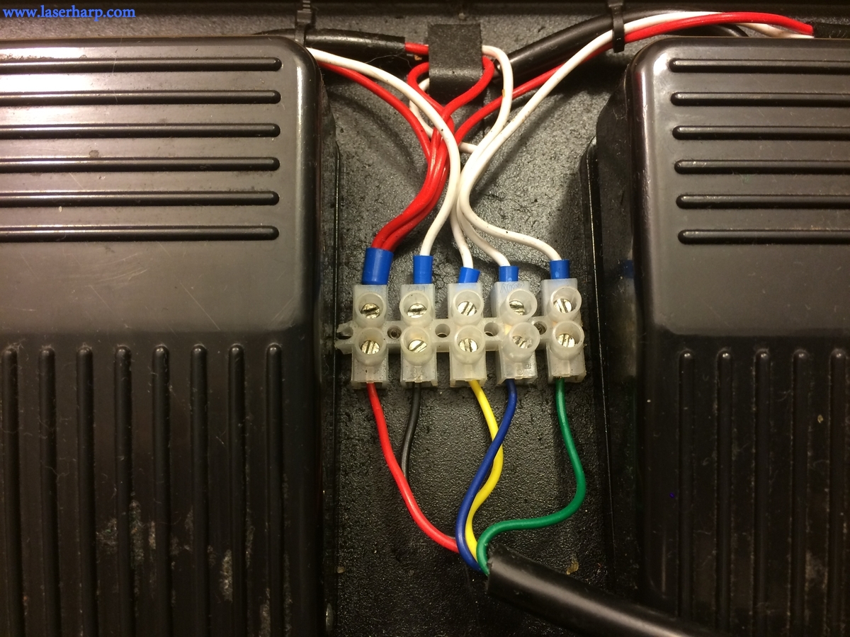
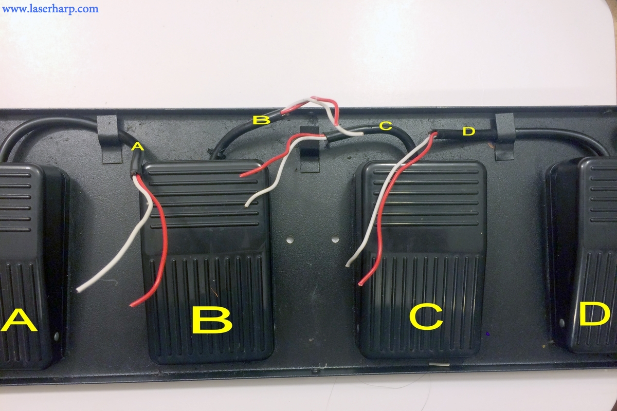
Solder each pair coming from the remote with the corresponding pair coming from the switch. There is no polarity, so it is enough to respect A,B,C,D sequence.
Check pressing each switch, the red Led on the remote must turn on.
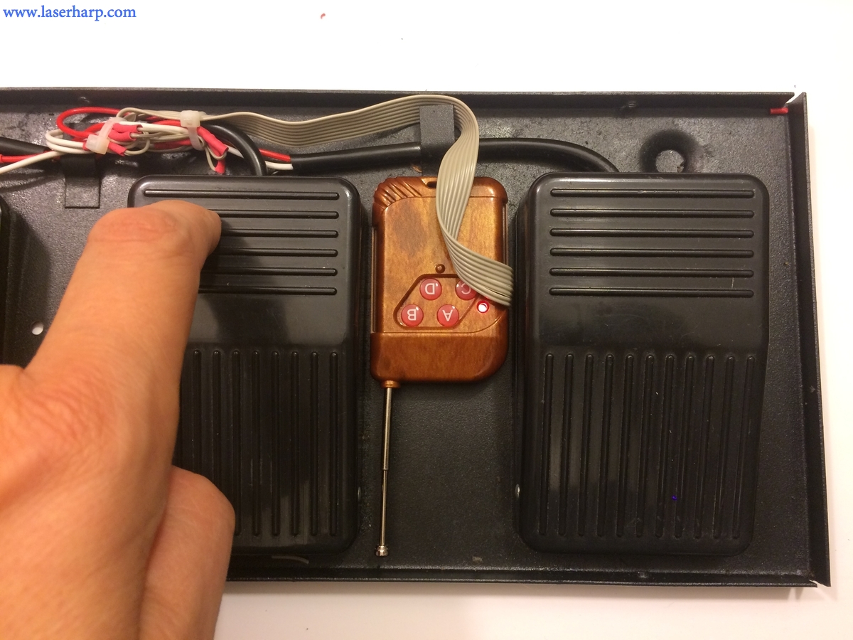
Find a suitable place to put the remote inside the footswitch, fasten with adesive tape and put the cover back. The footswitch is now ready.
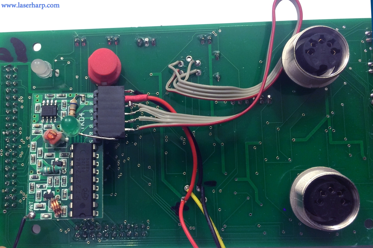
Now it's time to connect the receiver

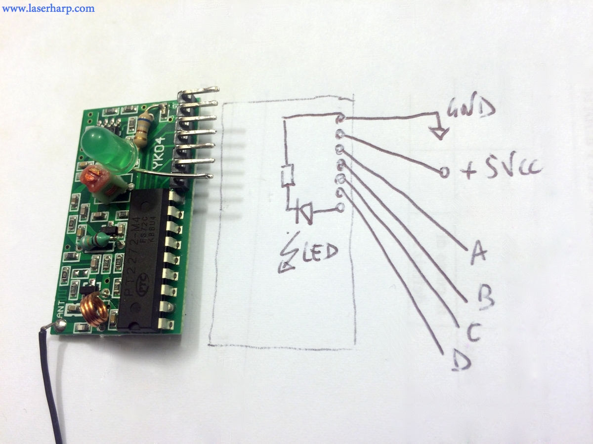
This module requires a supply voltage of at least 5V. We will take the 5Vcc supply form the EVO board.
We added an Led to the module as indicated in the schematics: The Led will lit when any switch will be pressed on the transmitter side.
The output pins d0,d1,d2,d3 are equivalent to A,B,C,D switches on transmitter side, as shown in this picture
Now let's have a look at the EVO board. The board and sensor come with a manual and schematics, so it is very easy to understand how to connect our receiver.
First we have to remove the DIN plugs on the panel. Well this is not really needed, we could solder wire on the back, but it made us comfortable to think that we will not use these connectors anymore since we are going wireless.
If you want to leave connectors in place, remember that on the back all connections are specular :)
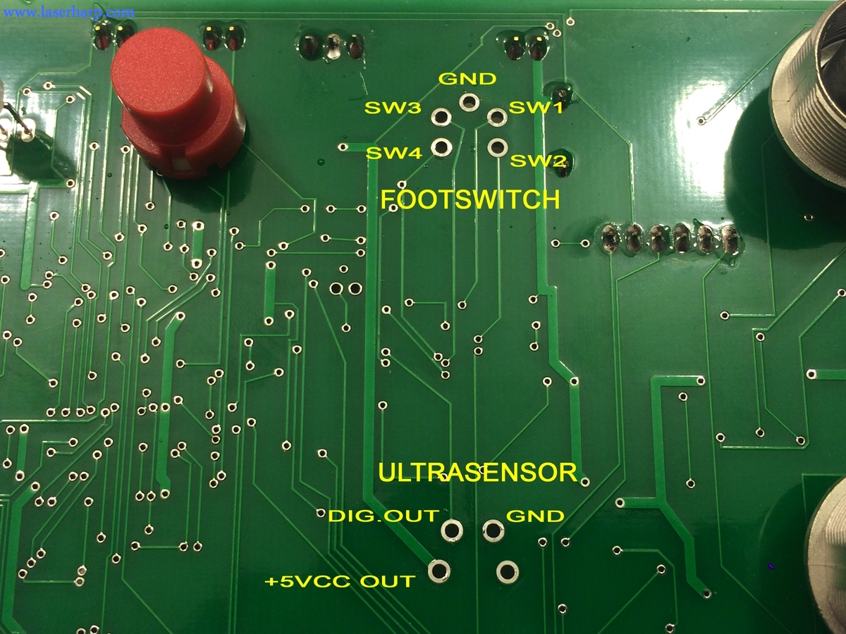
This is a picture of the back of the board:

The "Ultrasensor" connector has 4 pins, and 2 of them are used to supply power to the sensor. We will use these pins to supply the footswitch receiver and the Ultrasensor receiver (see the next article for this)
The Footswitch connector has the 4 pins that must be connected to Footswitch receiver (Sw1 = A, Sw2 = b, Sw3 = c, Sw4 = d)
This picture is taken from the front of the board:
Take care to insulate the receiver board from when placing it near the Evo board.
Test: give supply to EVO board following its manual's recommendation, and press a switch: the green led will lit. If it doesn't, something is wrong in power supply of the receiver.
With a meter, check voltage on receiver pins d0,d1,d2,d3 (a,b,c,d) of the receiver. Pressing the pedal A you should have voltage on pin d0 and so on. If everything is ok, you can turn connect the ILDA cable between the EVO board and your laser projector and press switches 1 and 4 together (they must be pressed together in the same time)
The laser harp should open, as described in the EVO manual.
We provide a ZIP with:
Kromalaser 3d-EVO manual
Updated firmware supporting these wireless modifications
Firmware upgrade software (follow manual to upgrade)
Transceivers data sheet
here:
Wireless Laser Harp Files